Prompted by earlier night-fall as we go into winter, and the prospect of travelling home in the dark for the next 4 or more months, I felt the need to become more visible on the motorway at dusk. Particularly in the heavy traffic heading north from Albany up to Silverdale on the motorway. On the bike there is an opportunity to lane-split carefully, but in the dusk period, it’s much harder for people to see bikes coming up from behind, lights often just look like a single side of car headlights. Without something creating a narrower shape, perhaps with amber lights creating a narrower-than-car visible boundary to the bike, it’s easy to understand how we just merge into the background of all of the other car lights in the mirrors…
Keen to find a way to stand out a little bit more as I filter through between cars, I dug out a set of LED lights which I’ve owned for some time now. I’ve never before put these to any use but I’ve always intended to do something with them.
The LED light modules which I bought (from ebay), have three LEDs on each light with a lens for each one. The lights can light, either as white, or pure amber – which is excellent, as they can be ‘work lights’ or a ‘beacon’ on the front of my bike. The challenge was to provide a way to control them, to set a mode for them to operate.
Since they’re going to be forward facing, I wanted to be able to have them on steady in either colour, as well as basic flashing in either colour, mixed colours, strobing, alternating etc. I also wanted them to be indicator aware in various modes, so that when the bike’s indicators are on, it will ‘silence’ the light mode, and will mimic the indicator pattern.
The most complex part of this for me was getting the P-Channel Mosfets (x3) all working, based on logic level (5V) outputs from the arduino. Previously when I’ve done this, and more commonly, N-Channel Mosfets are used, and they’re easier to put into place. However, in these LED modules, I could not control the ground, I needed to switch the positive, since the units use a common ground between both of the amber and white channels…
It meant I needed to go and buy some more components which I was able to do before the weekend. – So over this weekend, I put some proper time in to the programming, and the circuit layout.
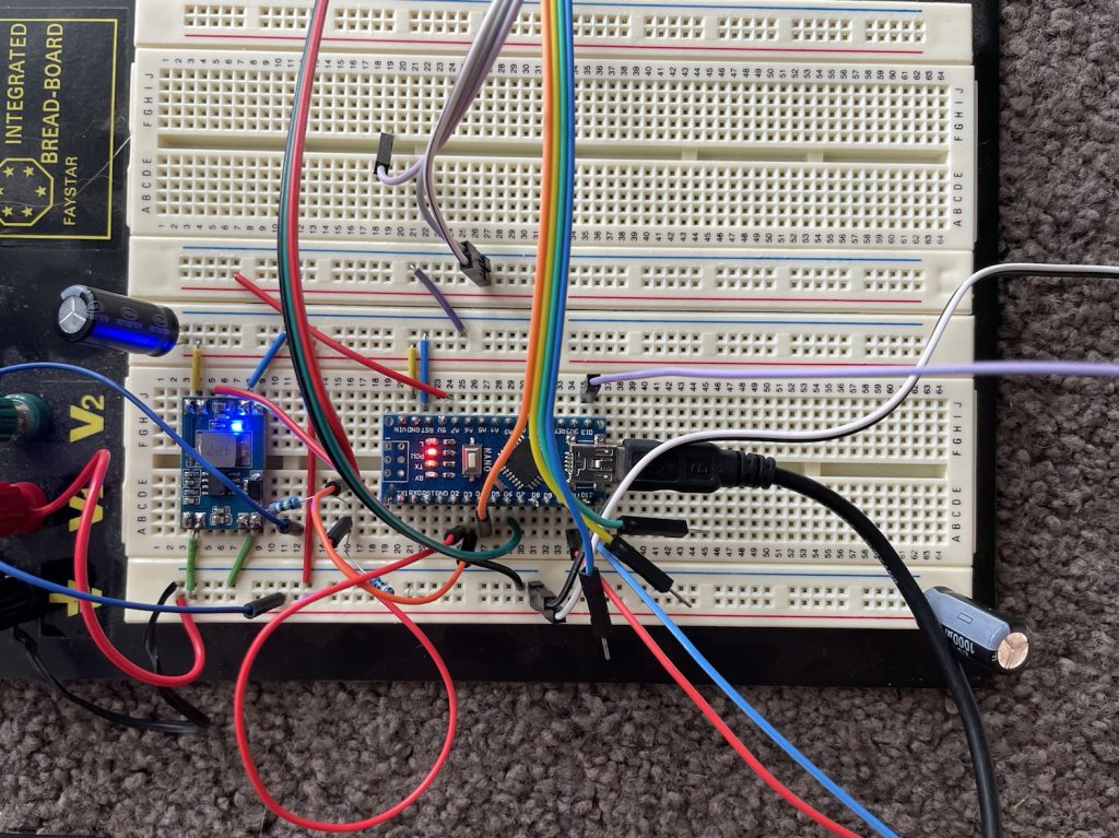
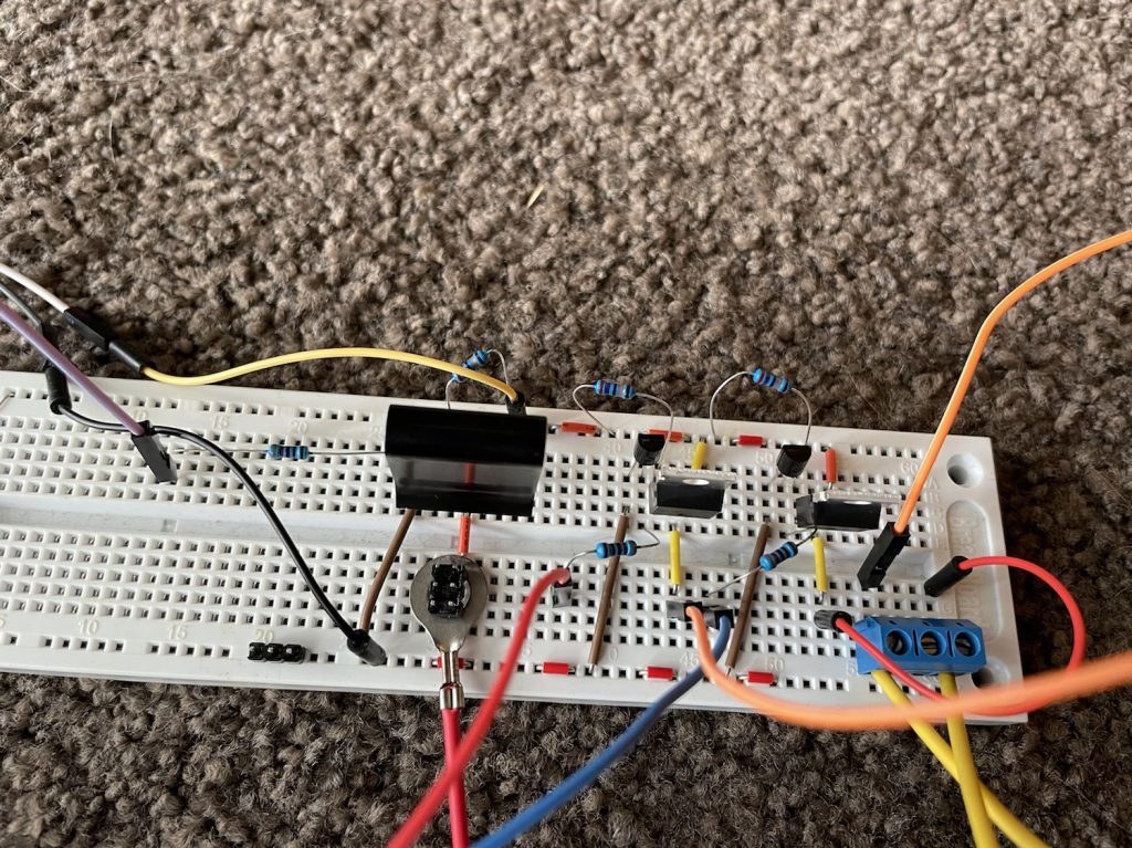
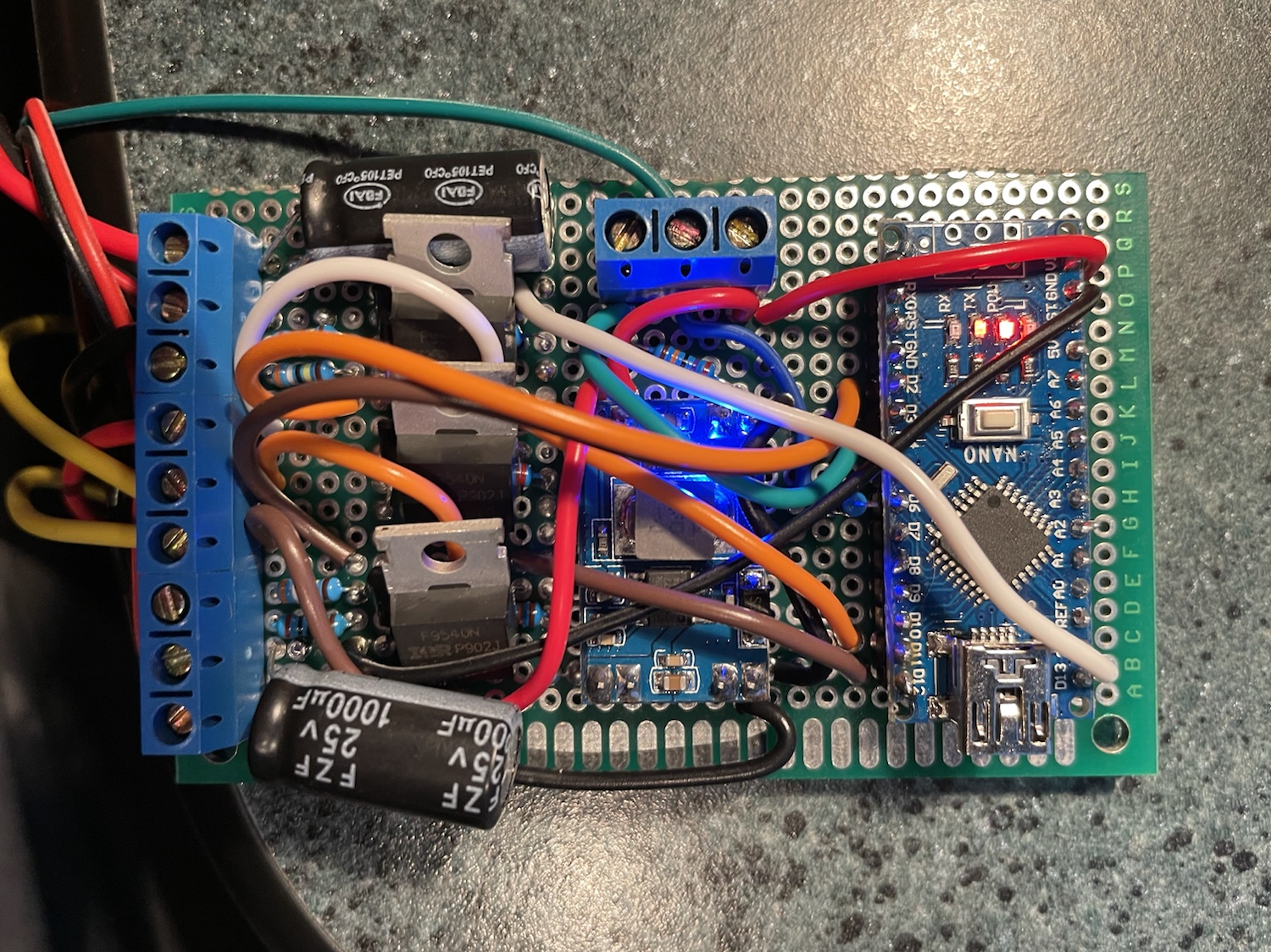
Initially on bread-board, and then I moved the circuits over to my prototyping board. The biggest challenge when moving it over to the prototyping board was the space consideration, I managed to cram it all into a nice small compact box which I’ll be able to conceal nicely on my bike behind one of the bits of fairing.

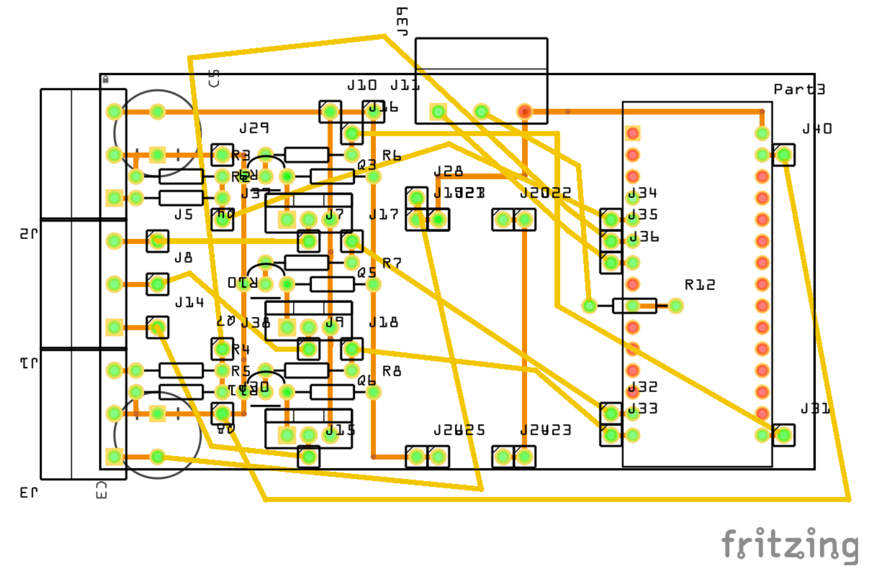
Here’s the prototyping board layout design: FlickerLightsC14 (PDF).
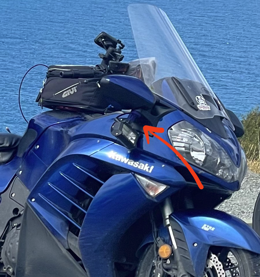
So this was all about the ‘making of it’, next video will be on the fitting of these to the bike. This is where they will be fitted: